Kategóriák: Minden - modeling - electromagnetic - communication - frequency

a patricia Alvarez 5 éve

261

Organigrama

Electromagnetic wave propagation is governed by fundamental principles described by Maxwell's equations, highlighting the interplay between changing electric and magnetic fields. This concept is crucial for understanding RF propagation, which can be effectively visualized using ray diagrams.
Organigrama

Introduction to RF propagation

Why Model Propagation?

The goal of propagation modeling is often to determine the probability of sat-isfactory performance of a communication system or other system that is dependent upon electromagnetic wave propagation. It is a major factor in communication network planning. If the modeling is too conservative, excessive costs may be incurred, whereas too liberal of modeling can result in. 10 INTRODUCTION * Sometimes called two-frequency simplex. In addition to signal strength, there are other channel impairments that can degrade link performance. These impairments include delay spread due to multipath and rapid signal fading within a symbol. These effects must be considered by the equipment designer, but are not generally considered as part of communica-tion link planning. Instead, it is assumed that the hardware has been ade-quately designed for the channel. In some cases this may not hold true and a communication link with sufficient receive signal strength may not perform well.

Propagation Effects as a Function of Frequency

The low frequency dictates that large antennas are required to achieve a reasonable efficiency. A good rule of thumb is that the antenna must be on the order of one-tenth of a wavelength or more in size to provide efficient performance. The VLF band only permits narrow bandwidths to be used . VLF has been successfully used with underground antennas for submarine communication. The low- and medium-frequency bands, cover the range from While the wavelengths are smaller than the VLF band, these bands still require very large antennas. Uses include broadcast AM radio and the WWVB time refer-ence signal that is broadcast at 60 kHz for automatic clocks. There are few remaining commercial uses due to unreliability, but HF sky waves were once the primary means of long-distance communication. One exception is international AM shortwave broadcasts, which still rely on ionospheric propagation to reach most of their listeners. CB radio is an example of poor frequency reuse planning. There can be tro-pospheric effects, however, when conditions are right. MODES OF PROPAGATION 9 Appli-cations of the SHF band include satellite communications, direct broadcast satellite television, and point-to-point links. Precipitation and gaseous absorp-tion can be an issue in these frequency ranges, particularly near the higher end of the range and at longer distances. The extra-high-frequency band covers 30–300 GHz and is often called millimeter wave. Most of the modeling covered in this book is for the VHF, UHF, SHF, and lower end of the EHF band. VHF and UHF work well for mobile communi-cations due to the reasonable antenna sizes, minimal sensitivity to weather, and moderate building penetration. These bands also have limited over-the-horizon propagation, which is desirable for frequency reuse. Typical ap-plications employ vertical antennas and involve communication through a centrally located, elevated repeater. The SHF and EHF bands are used primarily for satellite communication and point-to-point communications. This is sometimes called carrier-sensed multiple access when done automatically for data communi-cations, or push-to-talk in reference to walkie-talkie operation. Other techniques can be used to permit many users to share the same frequency allocation, such as time division multiple access and code division multiple access .

Ionospheric Propagation

In general, ionospheric effects are consid-ered to be more of a communication impediment rather than facilitator, since most commercial long-distance communication is handled by cable, fiber, or satellite. Ionospheric effects can impede satellite communication since the signals must pass through the ionosphere in each direction. Ionospheric prop-agation can sometimes create interference between terrestrial communica-tions systems operating at HF and even VHF frequencies, when signals from one geographic area are scattered or refracted by the ionosphere into another area. This is sometimes referred to as skip. The ionosphere consists of several layers of ionized plasma trapped in the earth’s magnetic field . [...] Figure 1.2 The ionospheric layers during daylight and nighttime hours. Frequency for any given path, below which the D layer attenuates too much signal to permit meaningful communication. Below 300 kHz, it will bend or refract RF waves, whereas RF above 4 MHz will be passed un-affected. The D layer is present during daylight and dissipates rapidly after dark. The E layer will either reflect or refract most RF and also disappears after sunset. Most satellite communication systems use circular polarization since alignment of a linear polarization on a satellite is difficult and of limited value in the presence of Faraday rotation. This can be a concern for ranging systems and systems that reply on wide bandwidths, since the group delay does vary with frequency. In fact the group delay is typically modeled as being proportional to 1/f 2. This distortion of wideband signals is called dispersion. Scintillation is a form of very rapid fading, which occurs when the signal attenuation varies over time, resulting in signal strength variations at the receiver. When a radio wave reaches the ionosphere, it can be refracted such that it radiates back toward the earth at a point well beyond the horizon. While the effect is due to refraction, it is often thought of as being a reflection, since that is the apparent effect. As shown in Figure 1.3, the point of apparent reflection is at a greater height than the area where the refraction occurs.

Tropospheric Propagation

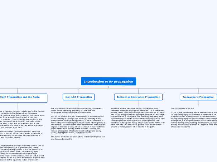
The troposphere is the first 10 km of the atmosphere, where weather effects exist. Tropospheric propagation consists of reflection of RF from temperature and moisture layers in the atmosphere. Tropospheric propagation is less reliable than ionospheric propagation, but the phenomenon occurs often enough to be a concern in frequency planning. Tropospheric propagation and ducting are discussed in detail in Chapter 6 when atmospheric effects are considered.

Indirect or Obstructed Propagation

While not a literal definition, indirect propagation aptly describes terrestrial propagation where the LOS is obstructed. In such cases, reflection from and diffraction around buildings and foliage may provide enough signal strength for meaningful communication to take place. The operating frequency has a significant impact on the viability of indirect propagation, with lower frequencies working the best. HF frequencies can penetrate buildings and heavy foliage quite easily. At the same time, VHF and UHF will have a greater tendency to diffract around or reflect/scatter off of objects in the path.

Non-LOS Propagation

The mechanisms of non-LOS propagation vary considerably, based on the operating frequency. At VHF and UHF frequencies, indirect propagation is often used. MODES OF PROPAGATION 5 phenomenon of electromagnetic waves bending at the edge of a blockage, resulting in the shadow of the blockage being partially filled-in. Refraction is the bending of electromagnetic waves due to inhomogeniety in the medium. Multipath is the effect of reflections from multiple objects in the field of view, which can result in many different copies of the wave arriving at the receiver. The over-the-horizon propagation effects are loosely categorized as sky waves, tropospheric waves, and ground waves. Sky waves are based on ionos-pheric reflection/refraction and are discussed presently.

Line-of-Sight Propagation and the Radio Horizon

Such a source is called an isotropic radiator and in the strictest sense, does not exist. As the distance from the source increases, the spherical wave front converges to a planar wave front over any finite area of interest, which is how the propagation is modeled. The direction of propagation at any given point on the wave front is given by the vector cross product of the electric field and the magnetic field at that point. The polarization of a wave is defined as the orientation of the plane that contains the E field. This cross product is called the Poynting vector. When the Poynting vector is divided by the characteristic impedance of free space, the resulting vector gives both the direction of propagation and the power density. The velocity of propagation through air is very close to that of free space, and the same value is generally used. When considering line-of-sight propagation, it may be necessary to consider the curvature of the earth . In particular, if the distance between the transmitter and receiver is large compared to the height of the antennas, then an LOS may not exist. The simplest model is to treat the earth as a sphere with a radius equivalent to the equatorial radius of the earth. Figure 1.1 LOS propagation geometry over curved earth. So the maximum link distance is approximately 24 miles.

Modes of Propagation

Electromagnetic wave propagation is described by Maxwell’s equations, which state that a changing magnetic field produces an electric field and a changing electric field produces a magnetic field. An introduction to the subject and some excellent references are provided in the second chapter. For most RF propagation modeling, it is sufficient to visual-ize the electromagnetic wave by a ray in the direction of propagation. This technique is used throughout the book and is discussed further in Chapter 2.

FREQUENCY DESIGNATIONS

Table 1.2 shows the nominal band designations and the official radar band designations in Region 2 as determined by international agreement through the International Telecommunications Union (ITU). RF propagation modeling is still a maturing field as evidenced by the vast number of different models and the continual development of new models. Most propagation models considered in this text, while loosely based on physics, are empirical in nature. Wide variation in environments makes definitive models difficult, if not impossible, to achieve except in the simplest of circumstances, such as free-space propagation.

Introduccion

As wireless systems become more ubiquitous, an understanding of radio- frequency (RF) propagation for the purpose of RF planning becomes increas- ingly important. Most wireless systems must propagate signals through nonideal environments. Thus it is valuable to be able to provide meaningful characterization of the environmental effects on the signal propagation. Since such environments typically include far too many unknown variables for a deterministic analysis, it is often necessary to use statistical methods for modeling the channel. Such models include computation of a mean or median path loss and then a probabilistic model of the additional attenuation that is likely to occur. What is meant by “likely to occur” varies based on application, and in many instances an availability figure is actually specified. While the basics of free-space propagation are consistent for all frequen- cies, the nuances of real-world channels often show considerable sensitivity to frequency. The concerns and models for propagation will therefore be heavily dependent upon the frequency in question. For the purpose of this text, RF is any electromagnetic wave with a frequency between 1 MHz and 300 GHz. Common industry definitions have RF ranging from 1 MHz to about 1 GHz, while the range from 1 to about 30 GHz is called microwaves and 30– 300 GHz is the millimeter-wave (MMW) region. This book covers the HF through EHF bands, so a more appropriate title might have been Introduc- tion to Electromagnetic Wave Propagation, but it was felt that the current title would best convey the content to the majority of potential readers.