によって Chuck Hellebuyck 3年前.
386
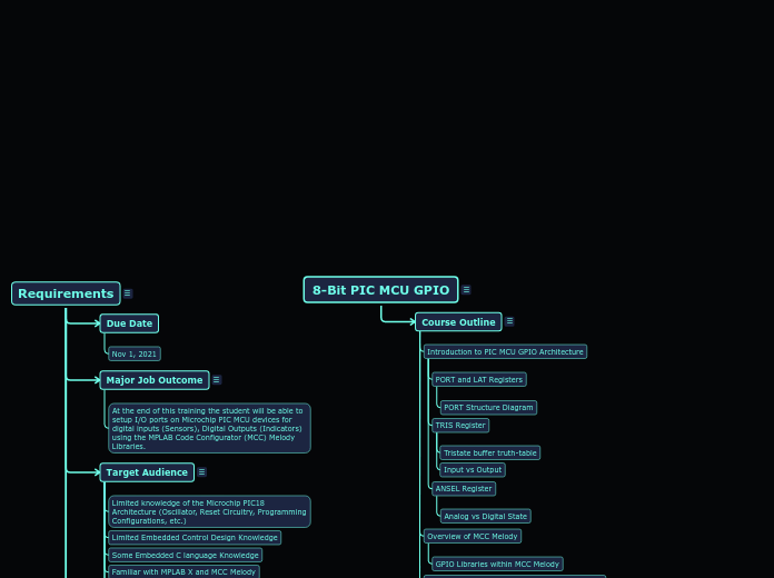
8-Bit PIC MCU GPIO
The document outlines the process and requirements for a training program focused on developing a custom LoRaWAN demo application using the SAMR34 Module. Key tasks include evaluating the SAMR34'

によって Chuck Hellebuyck 3年前.
386

もっと見る
Coaching Interview 1. Gather top-level project constraints.
Interview SME and sponsor to fill in each of the requested constraints.
What are the major engineering tasks required in order to accomplish the Job Outcome?
For a Job Outcome of "Custom LoRaWAN demo application using the SAMR34 Module", we could have the following tasks:
Course Type (Lecture-Only, Hands-On)?
Course Duration (Hours)?
Number of instructors required?
Who are the major audience groups the training is targeted to?
Expected background knowledge and experience level?
What will Attendees be able to produce or accomplish back on the job after taking this training? State it as a noun-phrase, for example:
"Customized LoRaWAN demo application using the SAMR34 Module"
This Class will cover all the features associated with the GPIO module in the 8-Bit PIC MCU Family. There will be Demonstrations to show how to set up the Peripheral for types of inputs and outputs. There will be discussions on where certain features will be useful in real world examples. And also cover common pitfalls you may encounter with GPIO.
Coaching Interview 3. Develop a Course Outline
From the Job/Task analysis, group content together into chapters and name the chapters.
"Knowledge" (Concept/Fact/Principle) bubbles map to "Lessons"
"Procedure" bubbles map to "Lab Exercises" or "Quizzes" or other hands-on activities.
Typically, a 1:1 relationship exists between Major Tasks and Chapters. However, you are free to group knowledge and procedures from several different Tasks into the same Chapter in the course outline.
When finished, the TTE will produce a course outline in word format that captures this structure.
Demonstrate Slew Rate Register
What is Slew Rate Control
Graphic images of Scope Plot or Similar
What is input Threshold
Graphic images of Scope Plot or similar
Purpose and when to use it
What is a Schmitt Trigger
Analog vs Digital State
Input vs Output
Tristate buffer truth-table
PORT Structure Diagram