Kategorier: Alla - binary - communication

av Qaisara Balqis för 5 årar sedan

1538

FUND COM TOPIC 11

The text discusses the various methods and codes used in the transmission of digital data within communication systems. It highlights the importance of efficient transmission, conversion, and reception techniques, driven by the proliferation of digital applications.
FUND COM TOPIC 11

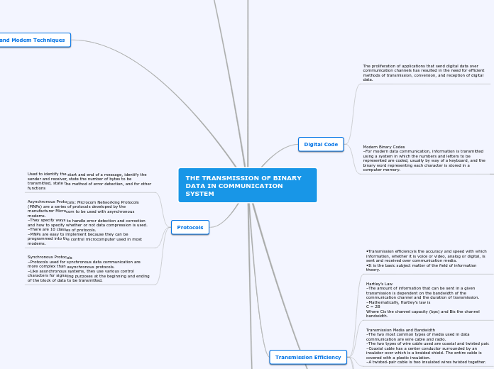
THE TRANSMISSION OF BINARY DATA IN COMMUNICATION SYSTEM

Protocols

Synchronous Protocols –Protocols used for synchronous data communication are more complex than asynchronous protocols. –Like asynchronous systems, they use various control characters for signaling purposes at the beginning and ending of the block of data to be transmitted.
Asynchronous Protocols: Microcom Networking Protocols (MNPs) are a series of protocols developed by the manufacturer Microcom to be used with asynchronous modems. –They specify ways to handle error detection and correction and how to specify whether or not data compression is used. –There are 10 classes of protocols. –MNPs are easy to implement because they can be programmed into the control microcomputer used in most modems.
Used to identify the start and end of a message, identify the sender and receiver, state the number of bytes to be transmitted, state the method of error detection, and for other functions

Broadband Modem Techniques

–Television channels extend from 50 MHz (Channel 2) up to 550 MHz. In this 500 MHz of bandwidth, up to 83 channels of 6 MHz can be accommodated. –The spectrum above the TV channels, from 550 to 850 MHz, is available for digital data transmission. Standard 6-MHz channels are used. –Cable modems use 64-QAM for downstream data. –Standard QPSK is used in the upstream channels.
During receive operations: 1.The signal is picked off the telephone line. 2.It is passed through the interface circuits. 3.Then it is fed to the receiver section. 4.It first encounters an adaptive equalizer. The adaptive equalizer adjusts itself automatically to compensate for the amplitude attenuation and distortion of the signal. 5.The signal is then demodulated, resulting in an NRZ serial digital signal. 6.This is passed through a descrambler, which produces the opposite effect of the transmit scrambler. 7.The descrambler output is the original serial data signal. This is sent to the UART, where it is translated to a parallel byte that the computer can store and use.
Analog Telephone Modem: Modem Operation During transmission operations: 1.The data to be transmitted is stored in the computer’s RAM. 2.It is formatted there by the communication software installed with the computer. 3.It is then sent 1 byte at a time to the modem. 4.The modem’s first job is to convert parallel data to serial data. This is done with shift registers. It is usually carried out by a universal asynchronous receiver/transmitter (UART),a digital IC that performs parallel-to-serial conversion for transmission and serial-to-parallel conversion for reception. 5.The serial data from the UART is passed through a scrambler circuit to ensure that the data is random. 6.The random serial data is sent to the modulator. 7.The output of the modulator is filtered to band-limit it and then fed to an equalizercircuit.
Analog Telephone Modem –The most commonly used modem is one that connects personal computers to the telephone line. –A typical dial-up modem consists of both transmitter and receiver sections. –Most modern modems are implemented using digital signal processing (DSP) techniques.

Basic Modem Concepts

QAM –One of the most popular modulation techniques used in modems for increasing the number of bits per baud is quadrature amplitude modulation (QAM). –QAM uses both amplitude and phase modulation of a carrier. –In 8-QAM, there are four possible phase shifts and two different carrier amplitudes. –Eight different states can be transmitted. –With eight states, 3 bits can be encoded for each baud or symbol transmitted. –Each 3-bit binary word transmitted uses a different phase-amplitude combination.
Phase-Shift Keying –In phase-shift keying (PSK),the binary signal to be transmitted changes the phase shift of a sine-wave character depending upon whether a binary 0 or binary 1 is to be transmitted. –A phase shift of 180°, the maximum phase difference that can occur, is known as a phase reversal,or phase inversion. –During the time that a binary 0 occurs, the carrier is transmitted with one phase; when a binary 1 occurs, the carrier is transmitted with a 180°phase shift.
Frequency-Shift Keying (FSK) –Frequency-shift keying (FSK)is the oldest and simplest form of modulation used in modems. –In FSK, two sine-wave frequencies are used to represent binary 0s and 1s. –A binary 0, usually called aspace, has a frequency of 1070 Hz. –A binary 1, referred to as a mark, is 1270 Hz. –These two frequencies are alternately transmitted to create the serial binary data.
There are four widely used modem types: 1.Conventional analog dial-up modems. 2.Digital subscriber line (DSL) modems. 3.Cable TV modems. 4.Wireless modems.
•Digital data are transmitted over the telephone and cable television networks by using broadband communication techniques involving modulation, which are implemented by a modem, a device containing both a modulator and a demodulator. •Modems convert binary signals to analog signals capable of being transmitted over telephone and cable TV lines and by radio, and then demodulate such analog signals, reconstructing the equivalent binary output.

Error Detection and Correction

Error Correction: Convolutional Codes –Convolutional encoding creates additional bits from the data as do Hamming and Reed Solomon codes, but the encoded output is a function of not only the current data bits but also previously occurring data bits. –Convolutional codes pass the data to be transmitted through a special shift register. –As the serial data is shifted through the shift register flip-flops, some of the flip-flop outputs are XORedtogether to form two outputs. –These two outputs are the convolutional code, and this is what is transmitted.The original data itself is not transmitted. –Instead, two separate streams of continuously encoded data are sent. –Since each output code is different, the original data can more likely be recovered at the receiver by an inverse process.
Error Correction: Block-Check Character –The block check character (BCC)is also known as a horizontal or longitudinal redundancy check (LRC). –It is the process of logically adding, by exclusive-ORing, all the characters in a specific block of transmitted data. –The final bit value for each horizontal row becomes one bit in a character known as the block-check character (BCC),or the block-check sequence (BCS). –The most popular FEC codes are the Hammingand Reed Solomoncodes. –These codes add extra parity bits to a transmitted word, process them using unique algorithms, and detect and correct bit errors. –Interleavingis a method used in wireless systems to reduce the effects of burst errors.
Many different methods have been used to ensure reliable error detection: •Redundancyis a method that ensures error-free transmission by sending each character or message multiple times until it is properly received. •Encoding schemeslike the RZ-AMI are used whereby successive binary 1 bits in the bit stream are transmitted with alternating polarity.

Wideband Modulation

Direct-Sequence Spread Spectrum –In a direct-sequence SS (DSSS)transmitter, the serial binary data is applied to an X-OR gate along with a serial pseudorandom code that occurs faster than the binary data. –One bit time for the pseudorandom code is called a chip,and the rate of the code is called the chipping rate.The chipping rate is faster than the data rate. –The signal developed at the output of the X-OR gate is then applied to a PSK modulator, typically a BPSK device.
Frequency-Hopping Spread Spectrum –In a frequency-hopping SS transmitter,the serial binary data to be transmitted is applied to a conventional two-tone FSK modulator. –The modulator output is applied to a mixer. –Also driving the mixer is a frequency synthesizer. –The output signal from the bandpass filter after the mixer is the difference between one of the two FSK sine waves and the frequency of the frequency synthesizer. –The synthesizer is driven by a pseudorandom code generator, which is either a special digital circuit or the output of a microprocessor.
–Spread spectrum (SS)is a modulation and multiplexing technique that distributes a signal and its sidebands over a very wide bandwidth. –After World War II, spread spectrum was developed by the military because it is a secure communication technique essentially immune to jamming. –Currently, unlicensed operation is permitted in the 902-to 928-MHz, 2.4-to 2.483-GHz, and 5.725-to 5.85-GHz ranges, with 1 W of power.
The two most widely used wideband modulation methods are spread spectrumand orthogonal frequency-division multiplexing.

Transmission Efficiency

Impact of Noise in the Channel –An important aspect of information theory is the impact of noise on a signal. –Increasing bandwidth increases the rate of transmission but also allows more noise to pass. –Typical communication systems limit the channel capacity to one-third to one-half the maximum to ensure more reliable transmission in the presence of noise.v
Multiple Coding Levels –Channel capacity can be modified by using multiple-level encoding schemes that permit more bits per symbol to be transmitted. –It is possible to transmit data using more than just two binary voltage levels or symbols. –Multiple voltage levels can be used to increase channel capacity. –Other methods, such as using different phase shifts for each symbol, are used.
Transmission Media and Bandwidth –The two most common types of media used in data communication are wire cable and radio. –The two types of wire cable used are coaxial and twisted pair. –Coaxial cable has a center conductor surrounded by an insulator over which is a braided shield. The entire cable is covered with a plastic insulation. –A twisted-pair cable is two insulated wires twisted together.
Hartley’s Law –The amount of information that can be sent in a given transmission is dependent on the bandwidth of the communication channel and the duration of transmission. –Mathematically, Hartley’s law is C = 2B Where Cis the channel capacity (bps) and Bis the channel bandwidth.
•Transmission efficiencyis the accuracy and speed with which information, whether it is voice or video, analog or digital, is sent and received over communication media. •It is the basic subject matter of the field of information theory.

Digital Code

Modern Binary Codes –For modern data communication, information is transmitted using a system in which the numbers and letters to be represented are coded, usually by way of a keyboard, and the binary word representing each character is stored in a computer memory.
Extended Binary Coded Decimal Interchange Code –The Extended Binary Coded Decimal Interchange Code (EBCDIC)was developed by IBM. –The EBDIC is an 8-bit code allowing a maximum of 256 characters to be represented. –The EBCDIC is used primarily in IBM and IBM-compatible computing systems and is not widely used as ASCII.
Hexadecimal Values –Binary codes are often expressed using their hexadecimal,rather than decimal values. –To convert a binary code to its hexadecimal equivalent, first divide the code into 4-bit groups. –Start at the least significant bit on the right and work to the left. (Assume a leading zero on each of the codes.)
American Standard Code for Information Interchange –The most widely used data communication code is the 7-bit binary code known as the American Standard Code for Information Interchange (ASCII). –ASCII code can represent 128 numbers, letters, punctuation marks, and other symbols. –ASCII code combinations are available to represent both uppercase and lowercase letters of the alphabet. –Several ASCII codes have two-and three-letter designations which initiate operations or provide responses for inquiries.
The proliferation of applications that send digital data over communication channels has resulted in the need for efficient methods of transmission, conversion, and reception of digital data.

Principles of Digital Transmission

Encoding Methods –Whether digital signals are being transmitted by baseband methods or broadband methods, before the data is put on the medium, it is usually encoded in some way to make it compatible with the medium. –In the non return to zero (NRZ)method of encoding the signal remains at the binary level assigned to it for the entire bit time. –In return to zero (RZ)encoding the voltage level assigned to a binary 1 level returns to zero during the bit period. –Manchesterencoding, also referred to as biphaseencoding, is widely used in LANs. In this system a binary 1 us transmitted first as a positive pulse, for one half of the bit interval, and then as a negative pulse for the remaining part of the bit interval.
Synchronous Transmission –The technique of transmitting each data word one after another without start and stop bits, usually in multiword blocks, is referred to as synchronous data transmission. –To maintain synchronization between transmitter and receiver, a group of synchronization bits is placed at the beginning and at the end of the block. –Each block of data can represent hundreds or even thousands of 1-byte characters. Synchronous Transmission –The special synchronization codes at the beginning and end of a block represent a very small percentage of the total number of bits being transmitted, especially in relation to the number of start and stop bits used in asynchronous transmission. –Synchronous transmission is therefore much faster than asynchronous transmission because of the lower overhead.
Asynchronous Transmission –In asynchronous transmissioneach data word is accompanied by startand stop bitsthat indicate the beginning and ending of the word. –When no information is being transmitted, the communication line is usually high, or binary 1. –In data communication terminology, this high level is referred to as a mark. –To signal the beginning of a word, a start bit, a binary 0 or space is transmitted.Asynchronous Transmission –Most low-speed digital transmission (the 1200-to 56,000-bps range) is asynchronous. –Asynchronous transmissions are extremely reliable. –The primary disadvantage of asynchronous communication is that the extra start and stop bits effectively slow down data transmission.
Expressing the Serial Data Rate –The speed of data transfer is usually indicated as number of bits per second (bps or b/s). –Another term used to express the data speed in digital communication systems is baud rate. –Baud rate is the number of signaling elements or symbols that occur in a given unit of time. –A signaling elementis simply some change in the binary signal transmitted.
Serial Transmission –Data can be transmitted in two ways: 1.Parallel 2.Serial –Data transfers in long-distance communication systems are made serially. –In a serial transmission, each bit of a word is transmitted one after another. –Parallel data transmission is not practical for long-distance communication.